THE CUSTOMER
Caps & closures producer
HTS SOLUTION
iTherm® conformal-cooled inserts
THE CHALLENGE
Uneven temperature distribution, slow stabilization and long cycle times
OUTCOME
26% cycle time reduction
Case study overview
HTS worked with a closures manufacturer that needed more uniform cavity cooling around critical regions, especially near the nozzle tip and the top surface, to reduce high temperatures and long cycle times.
We designed iTherm® conformally cooled inserts with two dedicated cooling loops (one focused on the gate/nozzle tip; another for the top surface), placing cooling channels much closer to the heat-dense areas.
Outcome Summary
Faster stabilization
Conventional system: needs ~5 cycles to reach quasi-steady state, indicating the point at which stable operating conditions are established.
iTherm®: stabilizes after only 2 cycles, saving time and energy.
Lower operating temperatures
Conventional: the temperatures at the end of the cycle remain around 45 °C, which exceeds the maximum recommended temperature specified by the material manufacturer.
iTherm®: the temperature distribution is significantly narrower, with the maximum average temperature limited to approximately 41 °C, thereby remaining within the acceptable range for the material.
Shorter cycle times & higher efficiency
Conventional: the expected cycle time is approximately 25 seconds, of which around 16 seconds are required for filling, packing, and cooling.
The conventional mold operates above the maximum temperature specified by the material datasheet, which means that the cycle must be prolonged in order to achieve a lower relative heat input and allow sufficient solidification.
iTherm®: the iTherm® solution reduces the overall cycle time to about 18.5 seconds. This improvement is achieved not only because the part solidifies more quickly, but also because the system dissipates heat at a rate that maintains operation within the approved material temperature range, thereby enabling true process optimization.
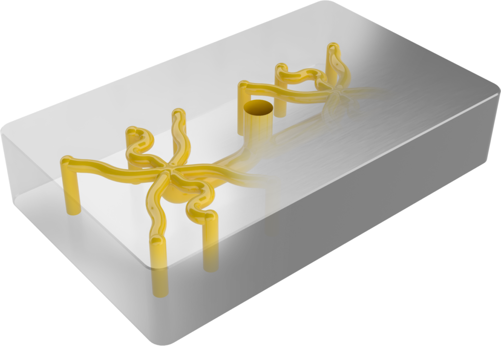
Geometry comparison
Gate

Manufactured with drilling and equipped with bubblers as coolant channels.
It uses eight bubblers connected in a series configuration.
Simplified design with two dedicated cooling loops. One loop is focused on the gate nozzle tips, while the second loop cools the top surface with targeted cooling lines directed at critical areas.
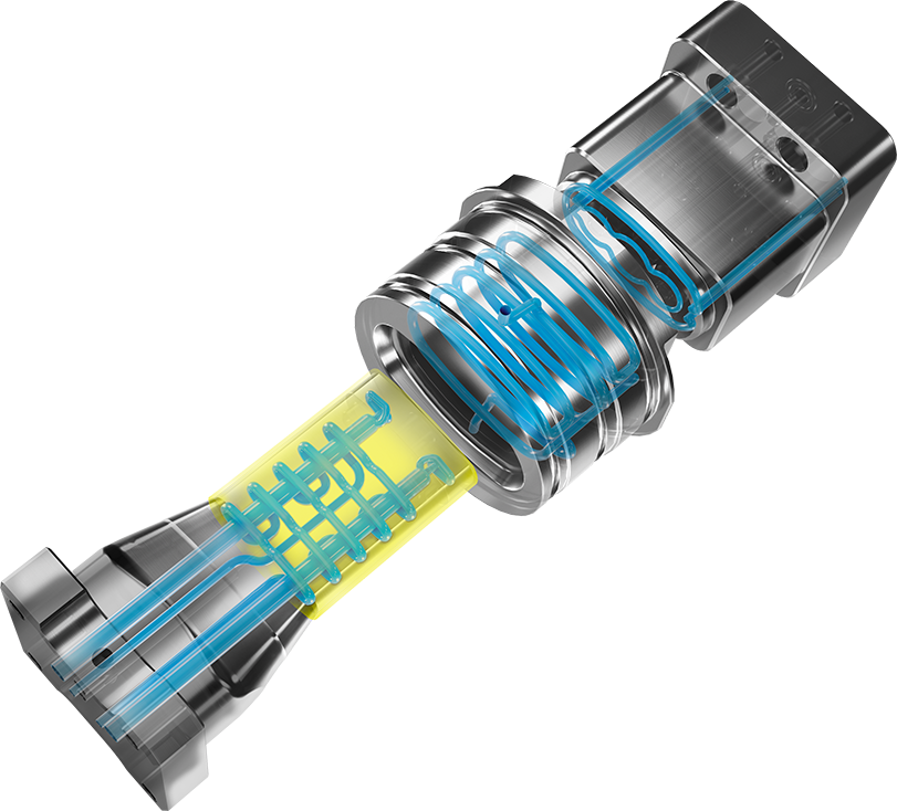
Side insert

With the conventional insert, the cooling loops are positioned far from the critical areas, which leads to less efficient and uneven cooling. In contrast, with the iTherm® solution, the cooling channels are placed much closer to the critical zones, allowing for more uniform and effective heat removal.
Core

The conventional solution has three bubblers connected in series. This serial connection causes the water to heat up as it flows from the first to the third bubbler, resulting in uneven cooling. In contrast, the iTherm® solution incorporates conformal channels that follow the 3D shape of the insert. These channels are placed much closer to the critical areas, ensuring significantly better heat dissipation.
OPERATING CONDITIONS | Material | PPCT 442xP |
|---|---|---|
Melt temperature | 240°C | |
Ejection temperature | 108°C | |
Max mold temperature (with the exception of gate) | 40°C | |
Cooling temperature | 30°C | |
Filling time | 1.3 s | |
Packing and cooling time | 15.7 s | |
Die open and ejection time | 5 s | |
Total cycle time | 22 s | |
Mold material | H11 | |
Thermal analysis
Channels
HEAT FLUX [J/cm2s]

When comparing heat flux and heat dissipation rates, the iTherm® solution demonstrates much more uniform and efficient cooling. In the conventional setup, many areas show little to no heat flux, resulting in poor heat transfer. On the other hand, the iTherm® design delivers a far more even heat distribution with significantly greater heat dissipation rates.
Gate
TEMPERATURE AT THE END OF CYCLE [ºC]

With the conventional gate insert, the maximum temperature exceeds 80 °C in the region surrounding the nozzle tip, which is typically the hottest area of the injection system. This location is also where the plastic part is expected to solidify last. However, the pronounced hotspot observed in this area contributes to an unnecessary prolongation of the cycle time.
The iTherm® solution exhibits little to no overheating, providing more controlled thermal conditions around the nozzle tip and thereby reducing cycle time while improving overall process efficiency.
Side insert
TEMPERATURE AT THE END OF CYCLE [ºC]

A similar issue is observed with the side insert, where a hotspot forms near the top edge of the part due to insufficient cooling. This limitation arises from the fact that, in the conventional design, the cooling lines are positioned too far from the critical region.
The iTherm® solution incorporates channels that are placed much closer to this area, resulting in a significantly improved temperature distribution and more effective thermal management.
Core
TEMPERATURE AT THE END OF CYCLE [ºC]

In the core insert, hotspots are observed around the edges with temperatures exceeding 45 °C. This is problematic, as the material datasheet specifies that the maximum allowable temperature should not surpass 40 °C. Such thermal excess can compromise both material performance and process reliability. In contrast, the iTherm® solution maintains a uniform thermal balance across the surface, effectively eliminating these hotspots and ensuring compliance with material temperature limits.
Part
TEMPERATURE AT THE END OF PACKING [ºC]

TEMPERATURE AT THE EJECTION [ºC]
At the end of the packing phase, the conventional insert exhibits pronounced hotspots near the nozzle tip, with temperatures reaching approximately 75 °C. These regions correspond to the last areas of the plastic part to solidify, thereby extending the overall cooling time.
The iTherm® solution substantially reduces the severity of these hotspots, resulting in a more uniform temperature distribution across the part and a more controlled solidification process.
Cavity surface avg. temperature

As shown in the cycle comparison, the conventional system requires at least five cycles to reach quasi-steady state, indicating the point at which stable operating conditions are established. Even at this stage, the temperatures at the end of the cycle remain around 45 °C, which exceeds the maximum recommended temperature specified by the material manufacturer.
In contrast, the iTherm® solution achieves quasi-steady state much more rapidly, stabilizing after only two cycles. Furthermore, the temperature distribution is significantly narrower, with the maximum average temperature limited to approximately 41 °C, thereby remaining within the acceptable range for the material.
See other case studies
Discover how customers improve part quality, decrease cycle times and improve productivity with iTherm® solutions.