Technology Brief
This case documents the development and simulation testing of a bi-material tooling insert – an internal R&D initiative by HTS.
A new generation of high-performance tooling inserts built as a true bi-material architecture that pushes mould cooling beyond conventional limits.
Why conventional conformal cooling hits a hard limit in injection moulding
Every mould engineer knows the math: cooling accounts for 60–80% of total cycle time. And when part geometry gets complex - deep cores, thin ribs, asymmetric sections - conventional straight-drilled cooling channels hit a hard physical limit. Hot spots persist, thermal gradients drive warpage, and no amount of process tuning can compensate for a heat path that simply isn't there.
Until now, the industry's options were incremental: optimise channel placement, adjust flow rates, experiment with high-conductivity alloys. All useful. None transformative.
Bi-material architecture: engineering for precise temperature distribution and heat extraction
This is where a new generation of bi-material tooling inserts breaks with convention. Rather than compromising between thermal performance and mechanical durability in a single material, this approach engineers them as two distinct, purpose-built layers - a concept that has no established precedent in production-grade injection mould tooling.
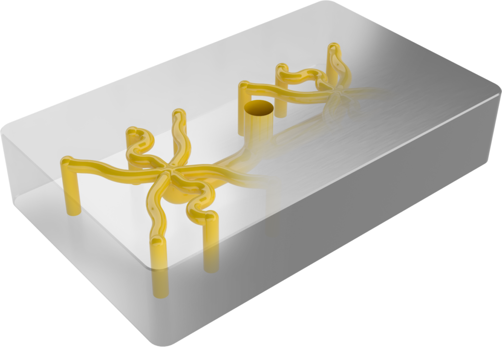
The core is a high-conductivity copper alloy with conformal cooling channels that follow the cavity geometry precisely, positioned to extract heat from the critical regions of the cavity. No straight-line compromises.
The shell is tool steel - delivering the hardness, wear resistance, and production durability expected from industrial tooling.
The performance lever is the heat path: a continuous, fully bonded copper–steel interface provides uninterrupted thermal contact from the cavity surface into the copper core and directly to the conformal cooling network.

The bonded copper–steel interface: eliminating thermal resistance at the heat extraction path
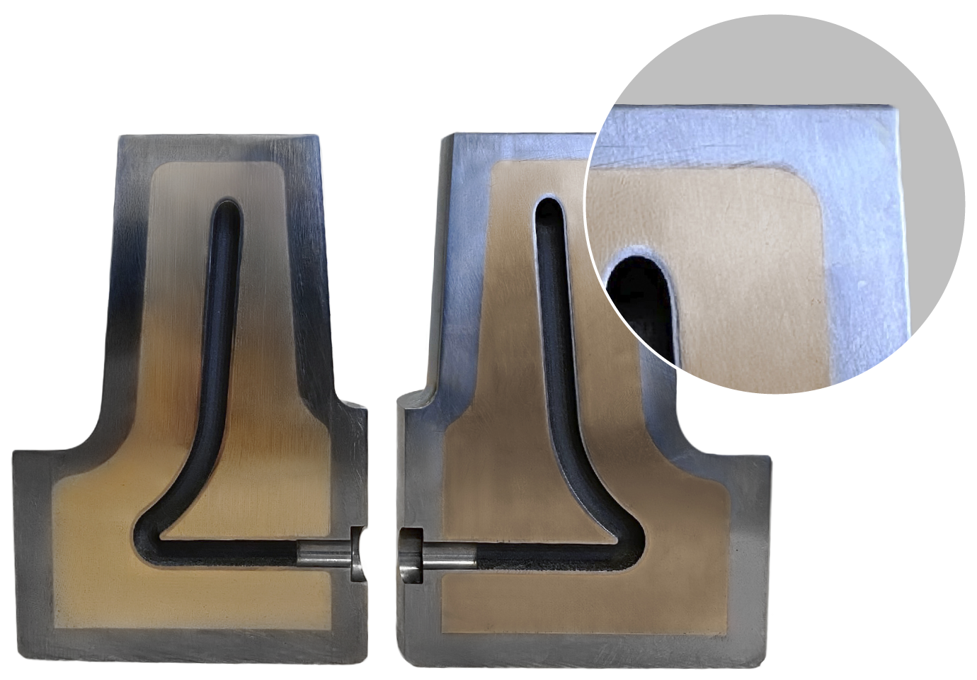
What elevates this beyond a simple material combination is the interface engineering. The copper-to-steel boundary is fully continuous and metallurgically bonded, creating an uninterrupted thermal pathway from the cavity surface, through the steel shell, into the copper core, and directly to the conformal cooling network.
This is the critical differentiator. Conventional approaches - press-fit cores, or copper plugs - invariably introduce contact resistance at the material boundary, limiting heat transfer at exactly the point where conductivity matters most.
By minimizing interfacial thermal resistance, heat is removed faster, which translates into a shorter cooling window, reduced thermal gradients, and a more stable process window.
Simulation-validated thermal performance: reduced thermal gradients, faster heat extraction

Figure 1. Cross-section temperature distribution during the solidification and cooling phase (baseline left vs high-conductivity core right).
Testing against a conventional baseline insert, the results are obvious:
ΔT across the working surfaces reduced by 37 °C – demonstrating a markedly more uniform cavity-side temperature field, with less hot–cold contrast across the functional area.
Heat extraction improved during the cooling phase – indicating higher effective heat flux out of the cavity so the plastic reaches solidification/ejection temperature sooner, supporting a shorter cooling window.
Thermal gradients are reduced with a more balanced temperature distribution – lowering localized thermal loading and helping stabilize part quality by reducing sensitivity to warpage and differential shrinkage.
Up to 25% projected productivity uplift via shorter cycle time – because cooling is typically the cycle-time bottleneck, faster and more uniform cooling translates directly into higher throughput when other cycle segments remain unchanged.
These are not marginal gains from process optimisation. They represent a step change in the mould's thermal response - the kind of shift that directly compresses the cooling window and widens the stable process envelope.
The cross-sectional temperature maps below compare an insert’s thermal field at two critical moments, during solidification and just before filling. They visualize how the thermal gradients collapse and the surface temperature uniformity improves across the working zone.

Figure 2. Cross-section temperature distribution immediately before the filling phase (baseline left vs high-conductivity core right).
Key takeaway: a higher-conductivity core increases the rate of heat dissipation, thereby lowering the mould surface temperature and improving thermal uniformity, shifting the process toward a wider stable operating window with shorter, more robust cooling.
What bi-material conformal cooling means for injection moulding productivity
For engineering teams that have already pushed cooling layouts, gate locations, and process parameters to their practical limits, bi-material inserts open a new degree of freedom in mould thermal design.
The projected impact: a cycle time reduction translating to approximately 25% higher productivity in suitable applications - particularly geometries where conventional cooling simply cannot reach the heat source effectively.
This is a genuine innovation in tooling architecture: decouple thermal performance from mechanical surface requirements, engineer each layer for its primary function, and deliver production-ready results. Copper moves the heat. Steel survives the process. The bonded interface makes it one system.
See other case studies
Discover how customers improve part quality, decrease cycle times and improve productivity with iTherm® solutions.